Random Items1. Single... ... 72. Lower port ... 73. Lower port ... 74. Amp HDM-20 ... 75. Overall... 76. Panel is... 77. Overall... 78. Fuse panel 2. ... 84. Blue...Random Images
Avelec fuel sender with 2 x 3 hole between headrestsDate: 09/07/2010 Views: 5366 
20040209204608_GDate: 12/31/1969 Views: 4599 
DSCF0012Date: 02/04/2009 Views: 5540 Newest Image
EAA SITEDate: 08/23/2023 Views: 784471 Most Viewed Image
EAA SITEDate: 08/23/2023 Views: 784471 |
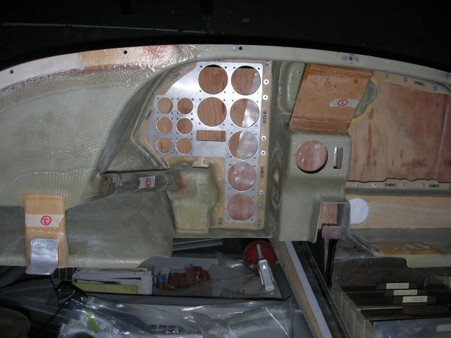
Photo Propertiessummary details
|