|
|
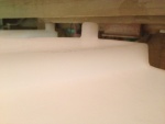
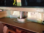
IMG_6985
And no amount of "coaxing" will prevail allowing entrance.
Date: 10/21/2013
Views: 10108
|
|
|
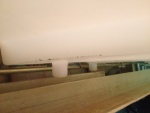
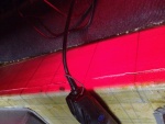
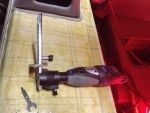
IMG_6989
In addition, the aileron tie rod between the sticks is in the way and will have to come out.
Date: 10/21/2013
Views: 12650
|
|
|
|
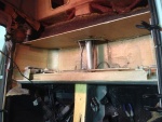
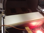
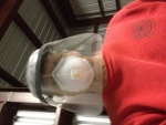
IMG_6991
Finally, that fore-aft support piece is also in the way and will have to come out.
Date: 10/21/2013
Views: 10638
|
|
|
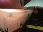
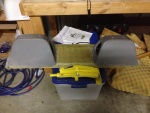
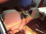
IMG_6982
The tank must go into this space.
Date: 10/21/2013
Views: 12774
|
|
|
|
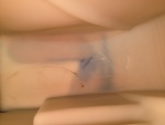
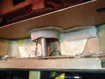
IMG_6973
In this view fore is down, aft is up, port to the right and starboard to the left.
Date: 10/18/2013
Views: 10177
|
|
|
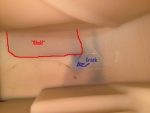
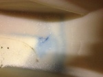
IMG_6973_em_sa
Here I have annotated the important elements. The red outlines the fiberglass support bonded to the bottom of the tank. Blue arrow points to the blue crack. The crack formed exactly as a stress analysis says it should, at 45º to the corner of that supp
Date: 10/18/2013
Views: 10047
|
|
|
|
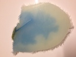
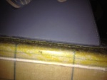
IMG_6975
The crack as viewed from the underside. it is about 1 5/8 in (4 cm) long and 1/32 in (1 mm) wide. Notice the blue staining on the underside surface.
Date: 10/19/2013
Views: 11534
|
|
|
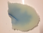
IMG_6978
The crack as viewed from the top side.
Date: 10/19/2013
Views: 10091
|
|
|
|
IMG_6972
Standing on the port side looking down into the tank. The leak is that blue line with the lighter blue background.
Date: 10/18/2013
Views: 10203
|
|
|
IMG_6977
The white stuff you see is low-expansion foam that was squirted in to provide support so this wouldn't happen. Unfortunately, I could not get foam under the port side sufficiently to support that side. That's where the crack developed.
Date: 10/19/2013
Views: 10499
|
|
|
|
IMG_6969
The top of the back rest removed. The rotary tool could not get into the area on the sides. A hacksaw blade was recruited for that effort. And it was an effort!
Date: 10/18/2013
Views: 10607
|
|
|
IMG_6971
The top of the old tank exposed. At this point the rotary tool was used to attack the old tank.
Date: 10/18/2013
Views: 9900
|
|
|
|
IMG_6976
At this point all that's left is that portion of the tank which was bonded to the back of the back rest.
Date: 10/19/2013
Views: 9923
|
|
|
IMG_6962
The cut on the front side
Date: 10/17/2013
Views: 11258
|
|
|
|
IMG_6966
Selfie of the protective gear needed. There was a LOT of fiberglass dust flying during the cutting.
Date: 10/17/2013
Views: 10489
|
|
|
IMG_6958
Tear out the interior to gain access to the upper part of the back where the fuel tank resides.
Date: 10/17/2013
Views: 10822
|
|
|
|
IMG_6960
The rotary tool that did most of the cutting. Front and rear sides of the back rest.
Date: 10/17/2013
Views: 10210
|
|
|
IMG_6961
The cut on the real side
Date: 10/17/2013
Views: 11074
|
|
|
|
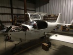
IMG_6960 1
One needs some room near the cockpit so the wings come off. In addition, all the connections to the fuel tank were removed.
Date: 11/10/2013
Views: 10488
|
|
|
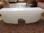
IMG_6957
Front side of the new tank.
Date: 10/17/2013
Views: 10221
|
|