|
|
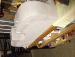
IMG_7027
The underside of the fuel tank is covered in plastic wrap which will prevent the tank from bonding to the epoxy in the micro.
Date: 10/30/2013
Views: 9991
|
|
|
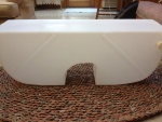
IMG_6956
Back side of the new tank.
Date: 10/17/2013
Views: 9896
|
|
|
|
IMG_7235
A strip being bonded to the front wall.
Date: 01/31/2014
Views: 10184
|
|
|
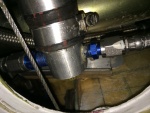
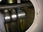
IMG_7356
The starboard side outlet with all fuel lines connected.
Date: 02/19/2014
Views: 9902
|
|
|
|
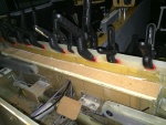
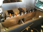
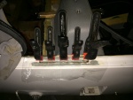
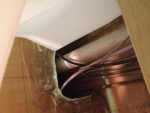
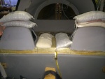
IMG_7232
Must have had the tank in/out two dozen times determining necessary clearances and supports.
Date: 01/26/2014
Views: 10957
|
|
|
IMG_7282
Two venting outlets.
Date: 02/13/2014
Views: 10744
|
|
|
|
IMG_7233
2-ply fiberglass strips were made up to be bonded to the inside of the unit. These strips went on all 4 sides. Here the strip is being bonded to the aft wall.
Date: 01/26/2014
Views: 12478
|
|
|
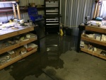
IMG_7536
It was a pretty good flow of water for a while. Flooding the back of the hanger. No real damage as, from previous experience, I try to keep things off the hanger floor in any case.
Date: 03/20/2014
Views: 13904
|
|
|
|
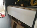
IMG_7704
And fixing the passenger side door sill.
Date: 05/02/2014
Views: 15374
|
|
|
IMG_6978
The crack as viewed from the top side.
Date: 10/19/2013
Views: 9906
|
|
|
|
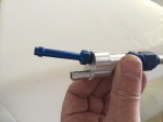
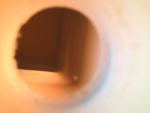
IMG_6855
But I can't get it past the entrance to the tank. Looks like I'll have to tear into things.
Date: 10/01/2013
Views: 10002
|
|
|
IMG_7285
The new sight gage running up the back rest. 2 P-clips hold it in place. The new sight gage is also back lit with a strip of LED lights.
Date: 02/13/2014
Views: 9916
|
|
|
|
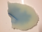
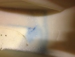
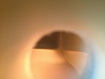
IMG_6972
Standing on the port side looking down into the tank. The leak is that blue line with the lighter blue background.
Date: 10/18/2013
Views: 9992
|
|
|
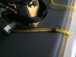
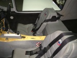
IMG_6996
You also have to make sure you clear all the cables, plumbing and wiring in the "tunnel" area.
Date: 10/21/2013
Views: 10247
|
|
|
|
IMG_7738
Everything pretty much back together. Eight months work at this point.
Date: 05/10/2014
Views: 20029
|
|
|
IMG_7365
Getting the sight gage plumbing in place.
Date: 02/22/2014
Views: 12429
|
|
|
|
IMG_6843
Back from KOSH, I get out my video snake and try to run it down into the tank to find the leak.
Date: 10/01/2013
Views: 11266
|
|
|
IMG_6956 1
With the tank removed, the micro and urethane could be covered with cork. The cork serves to protect the tank from abrasion by the support materials. You can also see the strip of urethane applied to the top of the aluminum support for the tank ledge.
Date: 11/10/2013
Views: 10418
|
|
|
|
IMG_7393
Shot bags (25 lbs each) to hold the top in place for the final bonding. 2 plies of fiberglass over a micro filler in the cut.
Date: 03/01/2014
Views: 10781
|
|
|
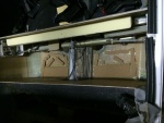
IMG_7314
The port side outlet installed. Fuel outlet to the fuel selector is on the starboard side and the outlet to the new sight gage on the port side.
Date: 02/17/2014
Views: 10075
|
|