|
|
IMG_6958
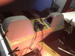
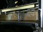
Tear out the interior to gain access to the upper part of the back where the fuel tank resides.
Date: 10/17/2013
Views: 10812
|
|
|
IMG_7373
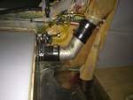
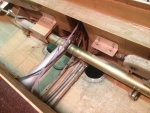
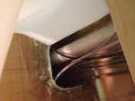
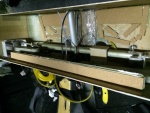
The vent system with all vent lines from the fuel sight gage and tank vents connected to the aircraft filler vent system.
Date: 02/22/2014
Views: 10767
|
|
|
|
IMG_6994
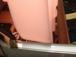
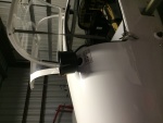
Seeing where the passenger door sill will have to be cut to allow the tank to go in.
Date: 10/21/2013
Views: 10667
|
|
|
IMG_7015
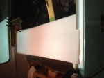
Finally, the new tank is in place. More or less.
Date: 10/23/2013
Views: 10660
|
|
|
|
IMG_7305
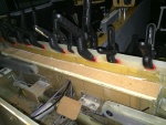
Checked, double checked and again checked all the fits.
Date: 02/16/2014
Views: 10651
|
|
|
IMG_7005
The space with the aileron tie rod and starboard side support removed.
Date: 10/22/2013
Views: 10636
|
|
|
|
IMG_6991
Finally, that fore-aft support piece is also in the way and will have to come out.
Date: 10/21/2013
Views: 10623
|
|
|
IMG_6969
The top of the back rest removed. The rotary tool could not get into the area on the sides. A hacksaw blade was recruited for that effort. And it was an effort!
Date: 10/18/2013
Views: 10598
|
|
|
|
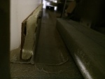
IMG_6956 1
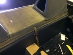
With the tank removed, the micro and urethane could be covered with cork. The cork serves to protect the tank from abrasion by the support materials. You can also see the strip of urethane applied to the top of the aluminum support for the tank ledge.
Date: 11/10/2013
Views: 10571
|
|
|
IMG_6977
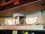
The white stuff you see is low-expansion foam that was squirted in to provide support so this wouldn't happen. Unfortunately, I could not get foam under the port side sufficiently to support that side. That's where the crack developed.
Date: 10/19/2013
Views: 10488
|
|
|
|
IMG_6960 1
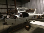
One needs some room near the cockpit so the wings come off. In addition, all the connections to the fuel tank were removed.
Date: 11/10/2013
Views: 10478
|
|
|
IMG_6966
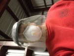
Selfie of the protective gear needed. There was a LOT of fiberglass dust flying during the cutting.
Date: 10/17/2013
Views: 10474
|
|
|
|
IMG_6996
You also have to make sure you clear all the cables, plumbing and wiring in the "tunnel" area.
Date: 10/21/2013
Views: 10442
|
|
|
IMG_7290
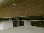
Bonded in the foam and cork support for the "ledge" at the front of the tank.
Date: 02/14/2014
Views: 10400
|
|
|
|
IMG_7315
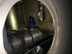
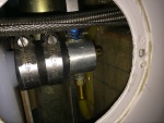
The starboard side outlet installed. Fuel outlet to the fuel selector is on the port side and fuel return from the engine is on the starboard side.
Date: 02/17/2014
Views: 10383
|
|
|
IMG_7235
A strip being bonded to the front wall.
Date: 01/31/2014
Views: 10365
|
|
|
|
IMG_7226
Here the urethane on the aluminum ledge has also been covered with cork. The cork both served to protect the tank and the urethane.
Date: 01/19/2014
Views: 10296
|
|
|
IMG_7374
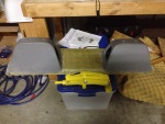
The filtering funnel keeps crap out of the fuel tank
Date: 02/22/2014
Views: 10269
|
|
|
|
IMG_7430
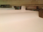
The front has bonded nicely around the sight gage entry.
Date: 03/11/2014
Views: 10252
|
|
|
IMG_7314
The port side outlet installed. Fuel outlet to the fuel selector is on the starboard side and the outlet to the new sight gage on the port side.
Date: 02/17/2014
Views: 10251
|
|