|
|
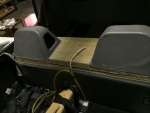
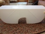
IMG_7319
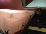
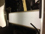
A test fit of the top. Check of the front.
Date: 02/17/2014
Views: 10229
|
|
|
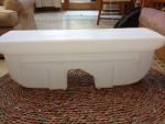
IMG_6957
Front side of the new tank.
Date: 10/17/2013
Views: 10214
|
|
|
|
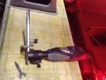
IMG_6960
The rotary tool that did most of the cutting. Front and rear sides of the back rest.
Date: 10/17/2013
Views: 10199
|
|
|
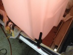
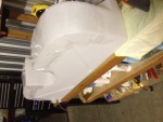
IMG_6984
But there's no way to get it in. It is too wide to go between the door sills.
Date: 10/21/2013
Views: 10186
|
|
|
|
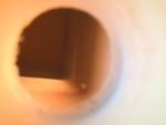
IMG_6855
But I can't get it past the entrance to the tank. Looks like I'll have to tear into things.
Date: 10/01/2013
Views: 10184
|
|
|
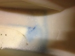
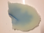
IMG_6972
Standing on the port side looking down into the tank. The leak is that blue line with the lighter blue background.
Date: 10/18/2013
Views: 10181
|
|
|
|
IMG_7027
The underside of the fuel tank is covered in plastic wrap which will prevent the tank from bonding to the epoxy in the micro.
Date: 10/30/2013
Views: 10174
|
|
|
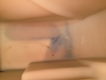
IMG_6973
In this view fore is down, aft is up, port to the right and starboard to the left.
Date: 10/18/2013
Views: 10165
|
|
|
|
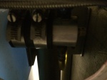
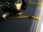
IMG_7383
Port fuel outlet . There was one small leak on the outlet to the fuel selector. I had wrenches ready, just in case, so it was easy to tighten that last bit to end the leak.
Date: 02/23/2014
Views: 10156
|
|
|
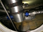
IMG_7356
The starboard side outlet with all fuel lines connected.
Date: 02/19/2014
Views: 10100
|
|
|
|
IMG_6985
And no amount of "coaxing" will prevail allowing entrance.
Date: 10/21/2013
Views: 10098
|
|
|
IMG_7281
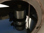
This picture illustrates how the new vent will be installed to obtain the best venting possible within the limits of the tank.
Date: 02/13/2014
Views: 10097
|
|
|
|
IMG_7285
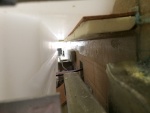
The new sight gage running up the back rest. 2 P-clips hold it in place. The new sight gage is also back lit with a strip of LED lights.
Date: 02/13/2014
Views: 10094
|
|
|
IMG_6978
The crack as viewed from the top side.
Date: 10/19/2013
Views: 10080
|
|
|
|
IMG_6956
Back side of the new tank.
Date: 10/17/2013
Views: 10060
|
|
|
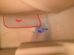
IMG_6973_em_sa
Here I have annotated the important elements. The red outlines the fiberglass support bonded to the bottom of the tank. Blue arrow points to the blue crack. The crack formed exactly as a stress analysis says it should, at 45º to the corner of that supp
Date: 10/18/2013
Views: 10039
|
|
|
|
IMG_7030
The tank was then put in place so that the urethane and micro could shape themselves to the bottom of the tank
Date: 10/31/2013
Views: 10023
|
|
|
IMG_6962
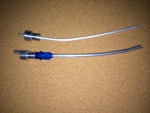
Old 1/4 in (6.4 mm) vent on the top. Totally inadequate for the job. New 3/8 in (9.5 mm) vent on the bottom.
Date: 11/13/2013
Views: 10008
|
|
|
|
IMG_7384
Starboard side fuel outlet. No leaks here
Date: 02/23/2014
Views: 10007
|
|
|
IMG_7231
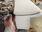
One final check to make sure everything fits and supports the tank.
Date: 01/26/2014
Views: 10000
|
|