|
|
IMG_7285
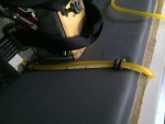
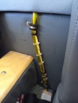
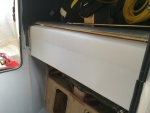
The new sight gage running up the back rest. 2 P-clips hold it in place. The new sight gage is also back lit with a strip of LED lights.
Date: 02/13/2014
Views: 9916
|
|
|
IMG_6995
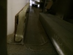
The cutout in the passenger door sill now allows entry of the tank.
Date: 10/21/2013
Views: 13869
|
|
|
|
IMG_7366
Applying the fiberglass/epoxy strips to the port side. Plastic wrap to prevent the epoxy from bonding to the tools used to hold the strip in place.
Date: 02/22/2014
Views: 12524
|
|
|
IMG_6956 1
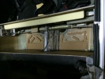
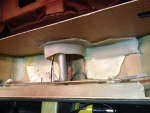
With the tank removed, the micro and urethane could be covered with cork. The cork serves to protect the tank from abrasion by the support materials. You can also see the strip of urethane applied to the top of the aluminum support for the tank ledge.
Date: 11/10/2013
Views: 10418
|
|
|
|
IMG_6966
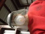
Selfie of the protective gear needed. There was a LOT of fiberglass dust flying during the cutting.
Date: 10/17/2013
Views: 10291
|
|
|
IMG_6969
The top of the back rest removed. The rotary tool could not get into the area on the sides. A hacksaw blade was recruited for that effort. And it was an effort!
Date: 10/18/2013
Views: 10462
|
|
|
|
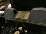
IMG_7305
Checked, double checked and again checked all the fits.
Date: 02/16/2014
Views: 10482
|
|
|
IMG_7767
The sight gage with calibration markers.
Date: 05/18/2014
Views: 13575
|
|
|
|
IMG_6858
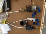
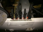
The old fittings as removed from the old tank. Vent on left, starboard outlet in the middle and port outlet on the right.
Date: 10/01/2013
Views: 11206
|
|
|
IMG_7232
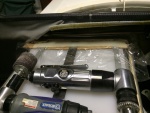
Must have had the tank in/out two dozen times determining necessary clearances and supports.
Date: 01/26/2014
Views: 10957
|
|
|
|
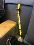
IMG_7770
Calibrated sight gage with LED illumination. This really does help identify the fuel level. FYI: 6 gal to the bottom of the lower P-Clip, 7 gal to the top of the P-Clip, 8 gal to the 1st white tie, 9 gal to the 2nd tie, 10 gal to the 1st black tie, 12 g
Date: 05/18/2014
Views: 14464
|
|
|
IMG_7319
A test fit of the top. Check of the front.
Date: 02/17/2014
Views: 10042
|
|
|
|
IMG_7335
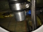
New sight gage connection clamped and fuel tight. The outlet to the fuel selector has been connected.
Date: 02/17/2014
Views: 10754
|
|
|
IMG_6977
The white stuff you see is low-expansion foam that was squirted in to provide support so this wouldn't happen. Unfortunately, I could not get foam under the port side sufficiently to support that side. That's where the crack developed.
Date: 10/19/2013
Views: 10326
|
|
|
|
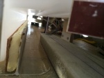
IMG_7029
Supporting material in the form of rigid polyurethane sheet and micro/epoxy mix are laid out on the bottom of the fuselage.
Date: 10/31/2013
Views: 9798
|
|
|
IMG_7704
And fixing the passenger side door sill.
Date: 05/02/2014
Views: 15374
|
|
|
|
IMG_6960 1
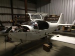
One needs some room near the cockpit so the wings come off. In addition, all the connections to the fuel tank were removed.
Date: 11/10/2013
Views: 10278
|
|
|
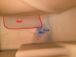
IMG_6973_em_sa
Here I have annotated the important elements. The red outlines the fiberglass support bonded to the bottom of the tank. Blue arrow points to the blue crack. The crack formed exactly as a stress analysis says it should, at 45º to the corner of that supp
Date: 10/18/2013
Views: 9894
|
|
|
|
IMG_7230
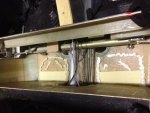
It was determined that a 1/4 in (6.4 mm) thick piece of rigid urethane foam topped with cork was needed to support the front "ledge" of the tank so it wouldn't sag.
Date: 01/26/2014
Views: 11530
|
|
|
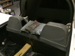
IMG_7730
Returned the upholstery on to the back.
Date: 05/09/2014
Views: 16279
|
|