|
|
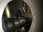
IMG_7315
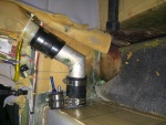
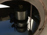
The starboard side outlet installed. Fuel outlet to the fuel selector is on the port side and fuel return from the engine is on the starboard side.
Date: 02/17/2014
Views: 10220
|
|
|
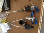
IMG_6858
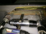
The old fittings as removed from the old tank. Vent on left, starboard outlet in the middle and port outlet on the right.
Date: 10/01/2013
Views: 11201
|
|
|
|
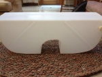
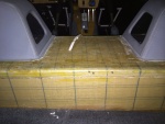
IMG_6956
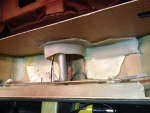
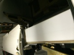
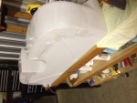
Back side of the new tank.
Date: 10/17/2013
Views: 9895
|
|
|
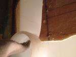
IMG_7014
Next catch was where the filler needed to go into its' position. There was a piece blocking which had to be removed.
Date: 10/23/2013
Views: 12333
|
|
|
|
IMG_7313
The filler neck and vent installed in the tank.
Date: 02/17/2014
Views: 10695
|
|
|
IMG_6977
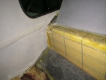
The white stuff you see is low-expansion foam that was squirted in to provide support so this wouldn't happen. Unfortunately, I could not get foam under the port side sufficiently to support that side. That's where the crack developed.
Date: 10/19/2013
Views: 10325
|
|
|
|
IMG_6855
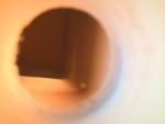
But I can't get it past the entrance to the tank. Looks like I'll have to tear into things.
Date: 10/01/2013
Views: 10000
|
|
|
IMG_6975
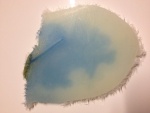
The crack as viewed from the underside. it is about 1 5/8 in (4 cm) long and 1/32 in (1 mm) wide. Notice the blue staining on the underside surface.
Date: 10/19/2013
Views: 11316
|
|
|
|
IMG_7321
Checking the back.
Date: 02/17/2014
Views: 13179
|
|
|
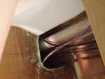
IMG_6996
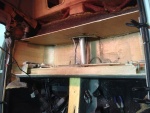
You also have to make sure you clear all the cables, plumbing and wiring in the "tunnel" area.
Date: 10/21/2013
Views: 10246
|
|
|
|
IMG_7030
The tank was then put in place so that the urethane and micro could shape themselves to the bottom of the tank
Date: 10/31/2013
Views: 9883
|
|
|
IMG_7735
Not as nice as it was but still not looking too shabby.
Date: 05/10/2014
Views: 13779
|
|
|
|
IMG_7322
Checking the back.
Date: 02/17/2014
Views: 12714
|
|
|
IMG_7367
Applying the fiberglass/epoxy strips to the starboard side.
Date: 02/22/2014
Views: 11018
|
|
|
|
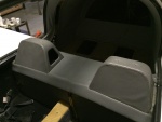
IMG_7282
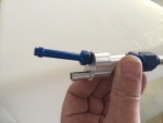
Two venting outlets.
Date: 02/13/2014
Views: 10743
|
|
|
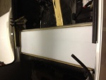
IMG_7312
With one final overall fit of the tank.
Date: 02/17/2014
Views: 13737
|
|
|
|
IMG_7384
Starboard side fuel outlet. No leaks here
Date: 02/23/2014
Views: 9852
|
|
|
IMG_7356
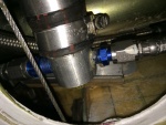
The starboard side outlet with all fuel lines connected.
Date: 02/19/2014
Views: 9901
|
|
|
|
IMG_6982
The tank must go into this space.
Date: 10/21/2013
Views: 12459
|
|
|
IMG_7027
The underside of the fuel tank is covered in plastic wrap which will prevent the tank from bonding to the epoxy in the micro.
Date: 10/30/2013
Views: 9987
|
|