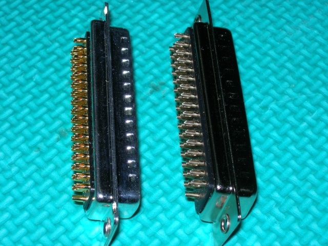
Here is a side by side comparison between a machined pin and folded metal pin solder pot connector. The machined pin on left is good for ~ 7 amps according to mfg. and folded pin 3 amps.
Price of 50 pin machined pin ~ 13$ and folded pin around 3$. Machined pin had nice gold plating and when connecting together feels nicer than folded pins.
Y10-06-11
Bob mentions he derates machined pins to 3 amps for Mach 3 operations:
At 04:16 PM 3/16/2011, you wrote:
>Bob,
>
> I realise I should test for myself, but
> thought it might apply to others:
>
> I am using a DB25 female and male pair for
> quick disconnect to accommodate up to #18 wire
> runs for future circuits in my instrument
> panel. [The whole panel OR each sub-panel is meant to be dismountable].
>
> Since it will hold up to 12 + and – runs, I
> measured the male pins at 0.04 inches in
> diameter from the pack of 100, labelled as
> `S604P’. These are solid, not stamped pins and sockets.
>
> Can I consider these to carry a constant 4
> amps if not bundled tightly together? AND could
> I parallel a set of three to carry a constant 10A in similar circumstances?
>
> I would like to know I’m operating in
> a`conservative’ milieu and don’t plan to run
> cfuture equipment at greater than 10A.
That works. When I qualified paralleled d-sub pins
onto this vehicle
I had to suffer the indignities of 70C environment at
full electrical loads. I de-rated the pins to 3A, paralleled
6 pins and handled three 20A input output pathways
on this solid state relay box.
So your suggestion of 3 pins to handle 10A is
as conservative that which flies at Mach 3
and 15 feet off the water. Things get really
warm on the launch stand . . . and warmer still
in flight through dense air.
Just keep your airplane below M3 and I think
you'll be just fine. I presume you understand
the necessity for 'ballasting' resistors in the
form of 12" of 22AWG in each pin path?
Bob . . .
At 05:33 PM 3/16/2011, you wrote:
>Further to my previous:
>
>A measured pin diameter is 0.04 inches, radius
>is 0.02â€, area is (0.02x0.02)xpi = 0.00125663
>sq.in. x 645.16 = 0.8107319 sq.mm.
>
>This comes out between AWG20 and AWG18 – call it AWG #19.
The pin diameter isn't much of a driver. It's localized
heating at the pin-spring interface inside the female
pin. 3A de-rating will give you VERY comfortable
performance.