|
|
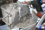
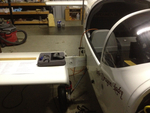
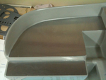
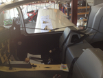
IMG_2513
Had to make up a new cover plate for the back of the transmission where alternator #2 formerly resided.
Date: 12/16/2011
Views: 5597
|
|
|
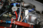
IMG_2437
Eventually, the 2nd alternator and supporting H/W will go. Also, I have Parahelion copper-clad aluminum fat wire which will replace the existing fat wire.
Date: 10/15/2011
Views: 5555
|
|
|
|
IMG_2460
Used our hydraulic punch to poke out the round holes. The rectangular holes were corner drilled and cut out with aircraft shears. Files were used to clean up the holes in shape and size.
Date: 10/27/2011
Views: 10562
|
|
|
IMG_2509
and 60 Kts on the airspeed (also a bit less)
Date: 02/28/2012
Views: 6432
|
|
|
|
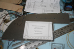
IMG_2451
Templates were used to transfer the instrument locations to the aluminum panels for cutting.
Date: 10/24/2011
Views: 7072
|
|
|
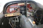
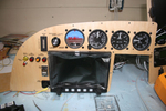
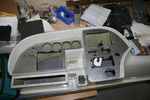
IMG_2526
Again a picture from a couple weeks ago. One of the initial test fit of the panel and check of wiring runs.
Date: 01/14/2012
Views: 5750
|
|
|
|
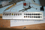
IMG_2447
Started to make up the switch and breaker panel.
Date: 10/24/2011
Views: 8212
|
|
|
IMG_2554
After a preliminary W&B done last week, the CG was now somewhat aft. After all, I had removed almost 40 lbs (18 Kilos) from the instrument panel and another 7 lbs (3 kilos) from the engine compartment. So I pulled the battery from below the baggage
Date: 02/21/2012
Views: 5575
|
|
|
|
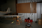
IMG_2491
Other wing. I'll only show a few of the pics from the annual.
Date: 02/24/2012
Views: 6088
|
|
|
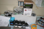
IMG_2452
The Garmin equipment sold very quickly and the proceeds were used to buy the new instruments. Here are the 2 1/2" "backup" gauges with the Microair Comm & Xponder as well as the GRT EIS 4000 from the old panel. At this point I was sti
Date: 10/24/2011
Views: 7643
|
|
|
|
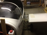
IMG_2512
Did numerous test fit insertions of the instrument panel shell. I think I finally have it ready to install.
Date: 12/16/2011
Views: 5542
|
|
|
IMG_2490
2012 Annual Condition Inspection. Opened it up and pulled the wings.
Date: 02/24/2012
Views: 5577
|
|
|
|
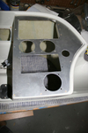
IMG_2313
Panel plates were cut from aluminum and fitted to the fiberglass.
Date: 10/06/2011
Views: 7618
|
|
|
IMG_2490
Altimeter has been installed. Added a USB port for the GRT Sport. Began the label process.
Date: 11/22/2011
Views: 5572
|
|
|
|
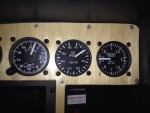
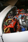
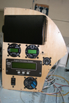
IMG_2495
496 Mount, Microair Comm & Xponder, GRT EIS 4000, Fuel Pressure, Prop Controls.
Date: 11/22/2011
Views: 5539
|
|
|
IMG_2456
Drilling for the rivets to hold the anchor nuts required novel technique. Eventually, all anchor nuts were installed.
Date: 10/25/2011
Views: 6885
|
|
|
|
IMG_2559
Add the 2 meter extension to the 1 meter length and run the viewer down to the brake area.
Date: 03/12/2012
Views: 6317
|
|
|
IMG_2461
The two main panels cut, poked and in place.
Date: 10/27/2011
Views: 10730
|
|
|
|
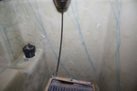
IMG_2582
Brought the pitot/static manometer out to test the P/S system.
Date: 02/27/2012
Views: 5565
|
|
|
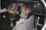
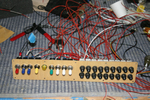
IMG_2468
Wiring begins in earnest. Color coding has been added to the switches. Red-Master, Blue-Ignition, Yellow-Starter, Green-Boost Pump & White-Lighting.
Date: 11/13/2011
Views: 5590
|
|