|
|
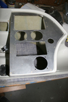
IMG_2451
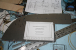
Templates were used to transfer the instrument locations to the aluminum panels for cutting.
Date: 10/24/2011
Views: 7072
|
|
|
IMG_2551
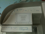
Today I installed the new cover for the console and began work on the brake plumbing. I need to replace the line from the reservoir to the master as it interferes with the trim switch. Replacement parts now on order.
Date: 02/21/2012
Views: 5667
|
|
|
|
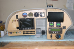
IMG_2065
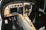
The GRT Sport has arrived and almost all the instruments have been set in their panels. This is a test fit. It was necessary to adjust the big opening in the main for clearance of some of the various instruments.
Date: 11/05/2011
Views: 8369
|
|
|
IMG_2509
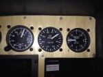
and 60 Kts on the airspeed (also a bit less)
Date: 02/28/2012
Views: 6432
|
|
|
|
IMG_2460
Used our hydraulic punch to poke out the round holes. The rectangular holes were corner drilled and cut out with aircraft shears. Files were used to clean up the holes in shape and size.
Date: 10/27/2011
Views: 10562
|
|
|
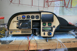
IMG_2501
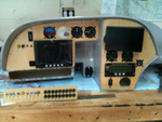
The full panel. Instrument final fit.
Date: 11/23/2011
Views: 6942
|
|
|
|
IMG_2470
Another test fit. Getting better. Still waiting on the electroluminescent light ring for the altimeter.
Date: 11/13/2011
Views: 5559
|
|
|
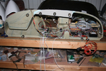
IMG_2523
But I'm still piddling around with the wiring and cabling. Found out today that the GRT Sport SX will control a Garmin SL30 radio and the Microair 760 will support SL30 type input/output. So, I'm working on adding the necessary wiring between the two.
Date: 01/03/2012
Views: 5518
|
|
|
|
IMG_2309
The obvious place to begin weight reduction was the ridiculously heavy instrument panel. Removed it and put the Garmin radios, etc. up for sale. Meanwhile, I began to lay out the instrument configuration in the old panel.
Date: 10/06/2011
Views: 10583
|
|
|
IMG_2463
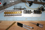
Here's why the bottom breakers are upside down. It puts the buss bars connecting the inputs together. The first breaker in the bottom row is the main output from the alternator so it is right side up so the output goes to the buss bars.
Date: 10/28/2011
Views: 6352
|
|