|
|
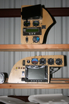
IMG_2461
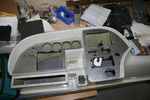
The two main panels cut, poked and in place.
Date: 10/27/2011
Views: 10970
|
|
|
IMG_2498
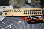
Switches and breakers have been labeled.
Date: 11/22/2011
Views: 5702
|
|
|
|
IMG_2490
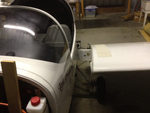
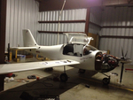
2012 Annual Condition Inspection. Opened it up and pulled the wings.
Date: 02/24/2012
Views: 5790
|
|
|
IMG_2508
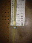
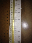
Tested every 20 kts from 40 Kts to 180 Kts. Here's 60 Kts on the manometer (actually a bit less)
Date: 02/28/2012
Views: 5695
|
|
|
|
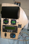
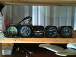
IMG_2495
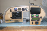
496 Mount, Microair Comm & Xponder, GRT EIS 4000, Fuel Pressure, Prop Controls.
Date: 11/22/2011
Views: 5731
|
|
|
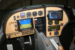
IMG_2545
Here's a decent picture of the new panel all lit up. As far as I can tell, everything works now. I still need to set up the GRT Sport SX, MicroAir 760 Radio and MicroAir T2000 Transponder.
Date: 02/20/2012
Views: 5759
|
|
|
|
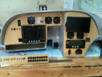
IMG_2065
The GRT Sport has arrived and almost all the instruments have been set in their panels. This is a test fit. It was necessary to adjust the big opening in the main for clearance of some of the various instruments.
Date: 11/05/2011
Views: 8585
|
|
|
IMG_2528
View from the other side. Must have down 5 test fit by the last one. Each resulted in finding things to correct. So I've been correcting things for a couple weeks now. More wire labels, adding connectors, checking pinouts, testing switches, finding is
Date: 01/14/2012
Views: 6168
|
|
|
|
IMG_2125
These 8 lbs of instruments were removed from the old panel along with the approximately 35 lbs of Garmin H/W.
Date: 11/24/2011
Views: 5731
|
|
|
IMG_2509
and 60 Kts on the airspeed (also a bit less)
Date: 02/28/2012
Views: 6631
|
|
|
|
IMG_2524
Maybe by the end of the week I can have the shell installed and wired into the aircraft so I can plug these into it. We'll see. These 26ºF (-3.3ºC) mornings have been limiting me to only 4 or 5 hours of afternoon work a day.
Date: 01/03/2012
Views: 5682
|
|
|
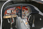
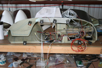
IMG_2525
Wiring in the instrument panel. From a couple weeks ago, not the final iteration.
Date: 01/14/2012
Views: 5688
|
|
|
|
IMG_2537
Here you can see the numerous check lists used in the inspections laid out on the wing.
Date: 03/02/2012
Views: 5893
|
|
|
IMG_2470
Another test fit. Getting better. Still waiting on the electroluminescent light ring for the altimeter.
Date: 11/13/2011
Views: 5733
|
|
|
|
IMG_2513
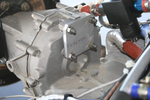
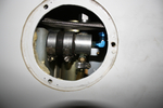
Had to make up a new cover plate for the back of the transmission where alternator #2 formerly resided.
Date: 12/16/2011
Views: 5794
|
|
|
IMG_2517
This is 160 Kts on the manometer (right on)
Date: 02/28/2012
Views: 5848
|
|
|
|
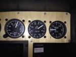
IMG_2452
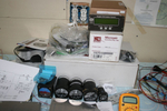
The Garmin equipment sold very quickly and the proceeds were used to buy the new instruments. Here are the 2 1/2" "backup" gauges with the Microair Comm & Xponder as well as the GRT EIS 4000 from the old panel. At this point I was sti
Date: 10/24/2011
Views: 7805
|
|
|
IMG_2571
Opened all the inspection holes to ensure all is well inside.
Date: 02/24/2012
Views: 6433
|
|
|
|
IMG_2312
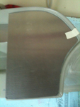
This was the more difficult fit of the three.
Date: 10/06/2011
Views: 11714
|
|
|
IMG_2313
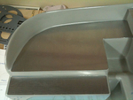
Panel plates were cut from aluminum and fitted to the fiberglass.
Date: 10/06/2011
Views: 7839
|
|