|
|
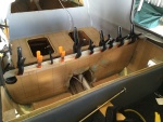
IMG_7233
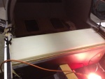
2-ply fiberglass strips were made up to be bonded to the inside of the unit. These strips went on all 4 sides. Here the strip is being bonded to the aft wall.
Date: 01/26/2014
Views: 5168
|
|
|
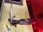
IMG_6960
The rotary tool that did most of the cutting. Front and rear sides of the back rest.
Date: 10/17/2013
Views: 3874
|
|
|
|
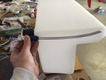
IMG_7281
This picture illustrates how the new vent will be installed to obtain the best venting possible within the limits of the tank.
Date: 02/13/2014
Views: 4655
|
|
|
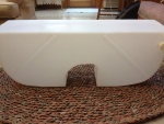
IMG_6956
Back side of the new tank.
Date: 10/17/2013
Views: 3841
|
|
|
|
IMG_7314
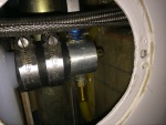
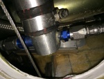
The port side outlet installed. Fuel outlet to the fuel selector is on the starboard side and the outlet to the new sight gage on the port side.
Date: 02/17/2014
Views: 4248
|
|
|
IMG_6966
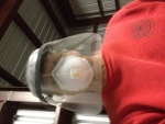
Selfie of the protective gear needed. There was a LOT of fiberglass dust flying during the cutting.
Date: 10/17/2013
Views: 3933
|
|
|
|
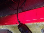
IMG_6996
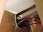
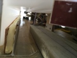
You also have to make sure you clear all the cables, plumbing and wiring in the "tunnel" area.
Date: 10/21/2013
Views: 4407
|
|
|
IMG_6977
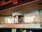
The white stuff you see is low-expansion foam that was squirted in to provide support so this wouldn't happen. Unfortunately, I could not get foam under the port side sufficiently to support that side. That's where the crack developed.
Date: 10/19/2013
Views: 4147
|
|
|
|
IMG_7356
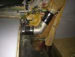
The starboard side outlet with all fuel lines connected.
Date: 02/19/2014
Views: 3896
|
|
|
IMG_7373
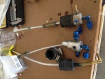
The vent system with all vent lines from the fuel sight gage and tank vents connected to the aircraft filler vent system.
Date: 02/22/2014
Views: 4371
|
|
|
|
IMG_7319
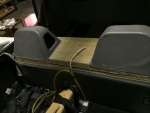
A test fit of the top. Check of the front.
Date: 02/17/2014
Views: 4003
|
|
|
IMG_6858
The old fittings as removed from the old tank. Vent on left, starboard outlet in the middle and port outlet on the right.
Date: 10/01/2013
Views: 4874
|
|
|
|
IMG_6971
The top of the old tank exposed. At this point the rotary tool was used to attack the old tank.
Date: 10/18/2013
Views: 3793
|
|
|
IMG_7230
It was determined that a 1/4 in (6.4 mm) thick piece of rigid urethane foam topped with cork was needed to support the front "ledge" of the tank so it wouldn't sag.
Date: 01/26/2014
Views: 5226
|
|
|
|
IMG_7027
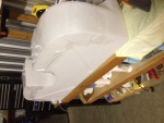
The underside of the fuel tank is covered in plastic wrap which will prevent the tank from bonding to the epoxy in the micro.
Date: 10/30/2013
Views: 3900
|
|
|
IMG_6957
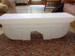
Front side of the new tank.
Date: 10/17/2013
Views: 3869
|
|
|
|
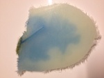
IMG_6975
The crack as viewed from the underside. it is about 1 5/8 in (4 cm) long and 1/32 in (1 mm) wide. Notice the blue staining on the underside surface.
Date: 10/19/2013
Views: 5195
|
|
|
IMG_6962
The cut on the front side
Date: 10/17/2013
Views: 4163
|
|
|
|
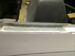
IMG_7712
Door sill repaired.
Date: 05/04/2014
Views: 5324
|
|
|
IMG_6843
Back from KOSH, I get out my video snake and try to run it down into the tank to find the leak.
Date: 10/01/2013
Views: 3892
|
|