|
|
IMG_6843
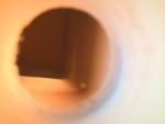
Back from KOSH, I get out my video snake and try to run it down into the tank to find the leak.
Date: 10/01/2013
Views: 3976
|
|
|
IMG_7367
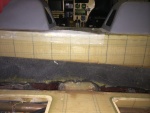
Applying the fiberglass/epoxy strips to the starboard side.
Date: 02/22/2014
Views: 4710
|
|
|
|
IMG_6973
In this view fore is down, aft is up, port to the right and starboard to the left.
Date: 10/18/2013
Views: 3916
|
|
|
IMG_6977
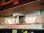
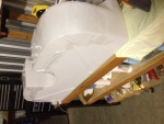
The white stuff you see is low-expansion foam that was squirted in to provide support so this wouldn't happen. Unfortunately, I could not get foam under the port side sufficiently to support that side. That's where the crack developed.
Date: 10/19/2013
Views: 4243
|
|
|
|
IMG_7373
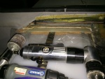
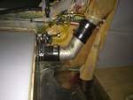
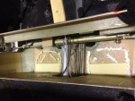
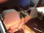
The vent system with all vent lines from the fuel sight gage and tank vents connected to the aircraft filler vent system.
Date: 02/22/2014
Views: 4477
|
|
|
IMG_6975
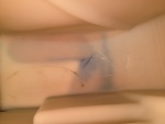
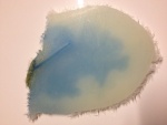
The crack as viewed from the underside. it is about 1 5/8 in (4 cm) long and 1/32 in (1 mm) wide. Notice the blue staining on the underside surface.
Date: 10/19/2013
Views: 5300
|
|
|
|
IMG_7770
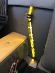
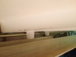
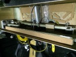
Calibrated sight gage with LED illumination. This really does help identify the fuel level. FYI: 6 gal to the bottom of the lower P-Clip, 7 gal to the top of the P-Clip, 8 gal to the 1st white tie, 9 gal to the 2nd tie, 10 gal to the 1st black tie, 12 g
Date: 05/18/2014
Views: 4729
|
|
|
IMG_7315
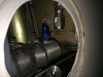
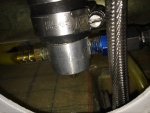
The starboard side outlet installed. Fuel outlet to the fuel selector is on the port side and fuel return from the engine is on the starboard side.
Date: 02/17/2014
Views: 4692
|
|
|
|
IMG_7029
Supporting material in the form of rigid polyurethane sheet and micro/epoxy mix are laid out on the bottom of the fuselage.
Date: 10/31/2013
Views: 4011
|
|
|
IMG_6855
But I can't get it past the entrance to the tank. Looks like I'll have to tear into things.
Date: 10/01/2013
Views: 4309
|
|
|
|
IMG_7027
The underside of the fuel tank is covered in plastic wrap which will prevent the tank from bonding to the epoxy in the micro.
Date: 10/30/2013
Views: 4003
|
|
|
IMG_6962
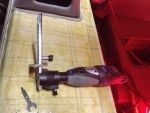
Old 1/4 in (6.4 mm) vent on the top. Totally inadequate for the job. New 3/8 in (9.5 mm) vent on the bottom.
Date: 11/13/2013
Views: 4183
|
|
|
|
IMG_7335
New sight gage connection clamped and fuel tight. The outlet to the fuel selector has been connected.
Date: 02/17/2014
Views: 5045
|
|
|
IMG_7438
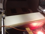
The back is well bonded across the width of the wall, as are the two sides.
Date: 03/11/2014
Views: 5458
|
|
|
|
IMG_6989
In addition, the aileron tie rod between the sticks is in the way and will have to come out.
Date: 10/21/2013
Views: 5601
|
|
|
IMG_6958
Tear out the interior to gain access to the upper part of the back where the fuel tank resides.
Date: 10/17/2013
Views: 4087
|
|
|
|
IMG_6960
The rotary tool that did most of the cutting. Front and rear sides of the back rest.
Date: 10/17/2013
Views: 3980
|
|
|
IMG_6971
The top of the old tank exposed. At this point the rotary tool was used to attack the old tank.
Date: 10/18/2013
Views: 3902
|
|
|
|
IMG_7226
Here the urethane on the aluminum ledge has also been covered with cork. The cork both served to protect the tank and the urethane.
Date: 01/19/2014
Views: 4026
|
|
|
IMG_7282
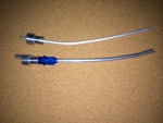
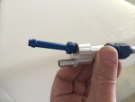
Two venting outlets.
Date: 02/13/2014
Views: 4643
|
|