|
|
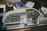
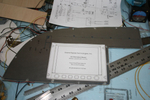
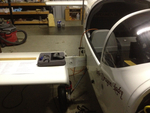
IMG_2461
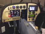
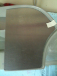
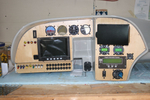
The two main panels cut, poked and in place.
Date: 10/27/2011
Views: 5799
|
|
|
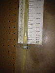
IMG_2508
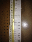
Tested every 20 kts from 40 Kts to 180 Kts. Here's 60 Kts on the manometer (actually a bit less)
Date: 02/28/2012
Views: 2796
|
|
|
|
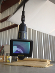
IMG_2559
Add the 2 meter extension to the 1 meter length and run the viewer down to the brake area.
Date: 03/12/2012
Views: 3706
|
|
|
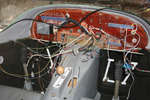
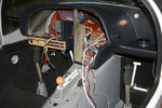
IMG_2522
Spent several weeks identifying and relabeling aircraft wiring. Talk about tedious...
Date: 01/03/2012
Views: 2916
|
|
|
|
IMG_2517
This is 160 Kts on the manometer (right on)
Date: 02/28/2012
Views: 2968
|
|
|
IMG_2456 1
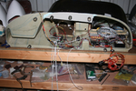
This is a picture from the first big "smoke test."
Date: 02/10/2012
Views: 2901
|
|
|
|
IMG_2523
But I'm still piddling around with the wiring and cabling. Found out today that the GRT Sport SX will control a Garmin SL30 radio and the Microair 760 will support SL30 type input/output. So, I'm working on adding the necessary wiring between the two.
Date: 01/03/2012
Views: 2821
|
|
|
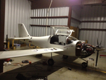
IMG_2538
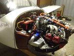
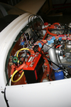
Uncowled engine open for inspection of all the wiring and plumbing and physical connections.
Date: 03/02/2012
Views: 3251
|
|
|
|
IMG_2312
This was the more difficult fit of the three.
Date: 10/06/2011
Views: 6811
|
|
|
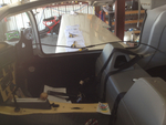
IMG_2554
After a preliminary W&B done last week, the CG was now somewhat aft. After all, I had removed almost 40 lbs (18 Kilos) from the instrument panel and another 7 lbs (3 kilos) from the engine compartment. So I pulled the battery from below the baggage
Date: 02/21/2012
Views: 2788
|
|
|
|
IMG_2470
Another test fit. Getting better. Still waiting on the electroluminescent light ring for the altimeter.
Date: 11/13/2011
Views: 3154
|
|
|
IMG_2524
Maybe by the end of the week I can have the shell installed and wired into the aircraft so I can plug these into it. We'll see. These 26ºF (-3.3ºC) mornings have been limiting me to only 4 or 5 hours of afternoon work a day.
Date: 01/03/2012
Views: 3160
|
|
|
|
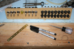
IMG_2451
Templates were used to transfer the instrument locations to the aluminum panels for cutting.
Date: 10/24/2011
Views: 4376
|
|
|
IMG_2526
Again a picture from a couple weeks ago. One of the initial test fit of the panel and check of wiring runs.
Date: 01/14/2012
Views: 2903
|
|
|
|
IMG_2565
You can see the bubbles of air coming from the brake line as you push fluid in from below. You can also manipulate the brake master to assist the flow of air out of the system.
Date: 03/12/2012
Views: 5095
|
|
|
IMG_2462
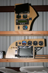
Here is the switch & breaker panel all nicely assembled. Don't know if you can tell, but the bottom row of breakers (except for the first one) are all upside down.
Date: 10/28/2011
Views: 3696
|
|
|
|
IMG_2491
Other wing. I'll only show a few of the pics from the annual.
Date: 02/24/2012
Views: 2945
|
|
|
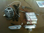
IMG_2123
And then another 7 lbs of alternator H/W and about 4 lbs of Whelen strobe/lights/power supply. That sleek piece in the lower left is one of the 6 oz AEROLED Nav/Strobe units replacing the Whelens.
Date: 11/24/2011
Views: 3131
|
|
|
|
IMG_2537
Here you can see the numerous check lists used in the inspections laid out on the wing.
Date: 03/02/2012
Views: 3189
|
|
|
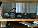
IMG_2125
These 8 lbs of instruments were removed from the old panel along with the approximately 35 lbs of Garmin H/W.
Date: 11/24/2011
Views: 3120
|
|