|
|
IMG_2309
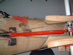
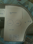
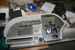
The obvious place to begin weight reduction was the ridiculously heavy instrument panel. Removed it and put the Garmin radios, etc. up for sale. Meanwhile, I began to lay out the instrument configuration in the old panel.
Date: 10/06/2011
Views: 10217
|
|
|
IMG_2307
Cardboard cutouts and templates were used to shape and size the panels and to decide where instruments should go.
Date: 10/06/2011
Views: 6541
|
|
|
IMG_2313
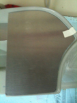
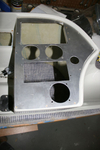
Panel plates were cut from aluminum and fitted to the fiberglass.
Date: 10/06/2011
Views: 7359
|
|
|
IMG_2312
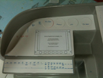
This was the more difficult fit of the three.
Date: 10/06/2011
Views: 10890
|
|
|
IMG_2451
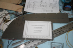
Templates were used to transfer the instrument locations to the aluminum panels for cutting.
Date: 10/24/2011
Views: 6846
|
|
|
IMG_2460
Used our hydraulic punch to poke out the round holes. The rectangular holes were corner drilled and cut out with aircraft shears. Files were used to clean up the holes in shape and size.
Date: 10/27/2011
Views: 10230
|
|
|
IMG_2461
The two main panels cut, poked and in place.
Date: 10/27/2011
Views: 10362
|
|
|
IMG_2452
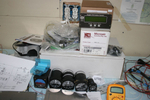
The Garmin equipment sold very quickly and the proceeds were used to buy the new instruments. Here are the 2 1/2" "backup" gauges with the Microair Comm & Xponder as well as the GRT EIS 4000 from the old panel. At this point I was sti
Date: 10/24/2011
Views: 7406
|
|
|
IMG_2447
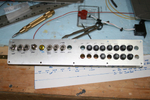
Started to make up the switch and breaker panel.
Date: 10/24/2011
Views: 7944
|
|
|
IMG_2456
Drilling for the rivets to hold the anchor nuts required novel technique. Eventually, all anchor nuts were installed.
Date: 10/25/2011
Views: 6660
|
